Concentric (formerly Haldex)
Concentric DC Power Hydraulic Power Units
Get Pricing & Availability
Womack Machine Supply Company proudly partners with Concentric (formerly Haldex) to deliver the finest Pumps available. Our commitment to excellence, combined with the reliability and performance of Concentric (formerly Haldex), guarantees that you receive top-quality Pumps components for your specific needs.
|
|
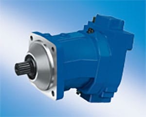
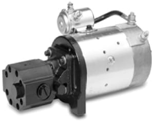
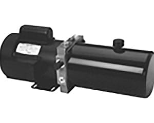
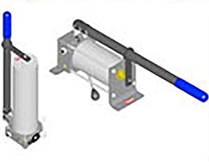
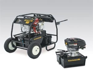
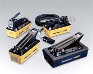
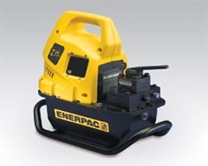
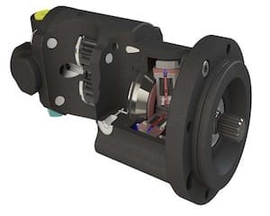
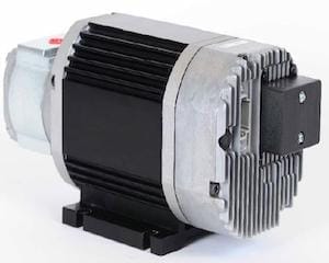
Description Our hydraulic power units are designed specifically to operate on DC electric power. Each power unit is a custom selected assembly consisting of a high performance hydraulic pump, reservoir, motor, internal relief valve, and load holding check valve. They can be controlled with remote valving, integral directional control or manual valves. The power units can be coupled via suitable hydraulic lines to a wide range of operating mechanisms. They normally operate hydraulic cylinders, but can be used with any other hydraulic actuating device. |

| DC HYDRAULIC POWER UNIT DIMENSIONS | |||
| Stock No. | Length | Width | Height |
| 1300754 | 20.4˝ | 6.7˝ | 10.5˝ |
| 1300751 | 20.2˝ | 6.0˝ | 7.3˝ |
| 1300757 | 20.4˝ | 6.0˝ | 7.3˝ |
- 12 or 24 VDC motors
- Adjustable relief valve preset at factory
- Load holding check valve
- Reservoirs plumbed for horizontal / vertical mount
- Various size cylindrical/rectangular reservoirs
- 9/16˝-18 SAE outlet and return ports, 1303835 = 1/4˝-18 NPTF ports
- 140 x 170 mesh inlet strainer
- See HE Power Packs catalog for complete options available
- Adaptor Kit 1303650 allows for 4-way, 2 & 3-Position circuits, stacked manifolds with D03 as an option.
- W300 high performance, pressure balance pumps are now available.
- Two-Stage, 5gpm High/low pump 1303698 is now available. 5 gpm @ 3600 rpm.
| DC HYDRAULIC POWER UNIT PERFORMANCE | |||||
| Distributor Stock No. | Nom. GPM | Oper. PSI | Motor Voltage | Nominal ON-TIME | Model Code / Description (Adapter) See following pages for Adapter details |
| 1300754 | 2.4 1.4 | 500 2000 | 12 12 | 66 secs on/234 off 36 secs on/264 off | HE2-BE000-72-173-A-80-AD-0-K-4-AE-0-B-00-00 Manual Lift-Hold-Lower |
| 1300751 | 2.4 1.4 | 500 2000 | 12 12 | 66 secs on/234 off 36 secs on/264 off | HE2-BB012-72-173-A-80-AD-0-K-2-AE-0-B-00-00 12 VDC Electric Lift-Hold-Lower |
| 1300757 | 2.4 1.4 | 500 2000 | 12 12 | 66 secs on/234 off 36 secs on/264 off | HE2-BA000-72-173-A-80-AD-0-K-2-AE-0-N-00-00 Base Unit |
| STANDARD POWER PACK | ||||||
| I | II | III | IV | V | VI | |
| ADAPTER SIZE | ADAPTER OPTIONS | PUMP TYPE / SIZE | RELIEF VALVE SETTING | FLOW CONTROL VALVE | MOTOR | |
| Example | HE2 | BH012 | 26 | 150 | E | 82 |
| Your Options | HE2 | |||||
| VII | VIII | IX | X | XI | XII | |
| RESERVOIR | MOTOR POSITION | START SWITCH | START SWITCH POSITION | TUBE KIT | BREATHER POSITION | |
| Example | AF | 6 | H | 2 | KC | 0 |
| Your Options | ||||||
| XIII | XIV | XV | XVI | |||
| COIL / LEVER POSITION | ACCESSORY | ACCESSORY | DESIGN SERIES | |||
| Example | N | 00 | 00 | A3 | ||
| Your Options | A3 | |||||
| THE HE 2000 POWER PACK EXAMPLE SHOWN ABOVE consists of a 3-position / 4-way valve, dual pilot-operated check valves, a 2.6 cc/rev. pressure-balanced pump, a 12 volt two terminal DC motor with start switch, and a 1.3 quart plastic reservoir. The relief valve has been set at 150 BAR (2175 PSI) and the power pack has a 1 gallon per minute (GPM) / 4 liter per minute (LPM) flow control valve incorporated into the return line circuit. The power pack is intended to be mounted in a vertical position with the motor terminals and breather cap opposite to PAD A. | ||||||
| I. ADAPTER SIZE | ||||||
| HE2 = HE 2000 | ||||||
| II. ADAPTER OPTIONS Pick a valve type and corresponding coil voltage, if applicable. | ||||||
| VALVE TYPE | KIT # | + COIL VOLTAGE | KIT # | |||
| BA | Adapter, P & T Ports, Relief Valve & Check Valve | Adapter Port Plug | 1303649 1300191 | BA000 | ||
| CA | Adapter, P & T Ports, Relief Valve & Check Valve | Adapter Port Plug AC Motor Adapte | 1303649 1300191 1303549 | CA000 | ||
| BB | Solenoid Lowering Adapter | Adapter Solenoid Release Valve | 1303649 1303534 | BB012* BB024* | 12 Volt DC 24 Volt DC | 1300914 1300915 |
| CB | Solenoid Lowering Adapter | Adapter Solenoid Release Valve AC Motor Adapter | 1303649 1303534 1303549 | CB115* CB230* CB012* CB024* | 115 Volt AC 230 Volt AC 12 Volt DC 24 Volt DC | 1303576 1303577 1300914 1300915 |
| BE | Manual Lowering Adapter w/DC Contactor | Adapter Manual Release Valve w/Pilot Contactor | 1303649 1300192 | BE000 | ||
| CE | AC Manual Lowering Valve Adapter | Adapter Manual Release Valve AC Motor Adapter | 1303649 1303533 1303549 | CE000 | ||
| Motor Spool (DC Version, AC Version and DC Version w/Double P.O. Check) | ||||||
| BF | Manifold Adapter w/3-Pos. 4-Way Valve (Motor Spool) DC Version | Adapter Manifold Motor Spool Valve Cavity Plug | 1303650 1300866 1303382 1303540 | BF012+ BF024+ | 12 Volt DC 24 Volt DC | 1300914 1300915 |
| BH | Manifold Adapter w/3-Pos. 4-Way Valve (Motor Spool) DC Version w/Double P.O. | Adapter Manifold Motor Spool Valve Double P.O.Check | 1303650 1300866 1303382 1303538 | BH012+ BH024+ | 12 Volt DC 24 Volt DC | 1300914 1300915 |
| CF | Manifold Adapter w/3-Pos. 4-Way Valve (Motor Spool) AC Version | Adapter Manifold Motor Spool Valve Cavity Plug Riser Block AC Motor Adapte | 1303650 1300866 1303382 1303540 1300855 1303549 | CF115+ CF230+ CF012+ CF024+ | 115 Volt AC 230 Volt AC 12 Volt DC 24 Volt DC | 1303576 1303577 1300914 1300915 |
| Tandem Center Spool (DC and AC Versions) | ||||||
| BJ | Manifold Adapter w/3-Pos. 4-Way Valve (Tandem Center Spool) DC Version | Adapter Manifold Tandem Center Valve Cavity Plug | 1303650 1300856 1303530 1303540 | BJ012+ BJ024+ | 12 Volt DC 24 Volt DC | 1300914 1300915 |
| CJ | Manifold Adapter w/3-Pos. 4-Way Valve (Tandem Center Spool) AC Version | Adapter Manifold Tandem Center Valve Cavity Plug Riser Block AC Motor Adapter | 1303650 1300856 1303530 1303540 1300855 1303549 | CJ115+ CJ230+ CJ012+ CJ024+ | 115 Volt AC 230 Volt AC 12 Volt DC 24 Volt DC | 1303576 1303577 1300914 1300915 |
| Solenoid Operated, 2-Position, 4-Way Normally Open Valve (DC and AC Versions) | ||||||
| BR | Manifold Adapter w/Sol. Operated, 2-Pos., 4-Way Valve DC Version | Adapter Manifold Normally Open Valve Cavity Plug | 1303650 1300856 1303529 1303540 | BR012* BR024* | 12 Volt DC 24 Volt DC | 1300914 1300915 |
| CR | Manifold Adapter w/Sol. Operated, 2-Pos., 4-Way Valve AC Version | Adapter Manifold Normally Open Valve Cavity Plug Riser Block AC Motor Adapter | 1303650 1300856 1303529 1303540 1300855 1303549 | CR115* CR230* CR012* CR024* | 115 Volt AC 230 Volt AC 12 Volt DC 24 Volt DC | 1303576 1303577 1300914 1300915 |
| BS | Manifold Adapter w/Sol. Operated, 2-Pos., 4-Way Valve DC Version w/P.O. Check | Adapter Manifold Normally Open Valve Single P.O. Check | 1303650 1300856 1303529 1303539 | BS012* BS024* | 12 Volt DC 24 Volt DC | 1300914 1300915 |
| Single D03 Valve Manifold (DC and AC Versions) / Double D03 Valve Manifold (AC Version Only) | ||||||
| DA | Manifold Adapter w/ Single D03 Valve Manifold DC Version | Adapter D03 Manifold Bolts | 1303650 1300854 1300865 | DA000 | ||
| DB | Manifold Adapter w/ Single D03 Valve Manifold AC Version | Adapter D03 Manifold Bolts Riser Block AC Motor Adapter | 1303650 1300854 1300857 1300855 1303549 | DB000 | ||
| DC | Manifold Adapter w/ Double D03 Valve Manifold AC Version Only | Adapter D03 Manifolds (2) Bolts Riser Block AC Motor Adapter | 1303650 1300854 (2) 1300858 1300855 1303549 | DC000 | ||
| DM | Manifold Adapter (DC Version) | Adapter | 1303650 | DM000 | ||
| AM | Manifold Adapter (AC Version) | Adapter AC Motor Adapter | 1303650 1303549 | AM000 | ||
| * Quantity of 1 needed. + Quantity of 2 needed. NOTE: AC coils have 36 inch cables. All DC coils have dual spades. | ||||||
| III. PUMP TYPE/SIZE (/REV. | MAX. PRESSURES | ||||||
| Order Code | Cm. | In. | Kit # | Continuous | Intermittent | ||
| W Series Pumps | PSI | BAR | PSI | BAR | |||
| 08 | 0.8 | .049 | 1303435 | 3335 | 230 | 3698 | 255 |
| 12 | 1.2 | .073 | 1303436 | 3335 | 230 | 3698 | 255 |
| 16 | 1.6 | .098 | 1303437 | 3335 | 230 | 3698 | 255 |
| 20 | 2.0 | .122 | 1303438 | 3335 | 230 | 3698 | 255 |
| 26 | 2.6 | .153 | 1303439 | 3335 | 230 | 3698 | 255 |
| 32 | 3.2 | .195 | 1303440 | 3335 | 230 | 3698 | 255 |
| 38 | 3.8 | .232 | 1303441 | 3045 | 210 | 3335 | 230 |
| 43 | 4.3 | .262 | 1303442 | 2755 | 190 | 3045 | 210 |
| 48 | 4.8 | .293 | 1303443 | 2465 | 170 | 2712 | 187 |
| 57 | 5.7 | .348 | 1303444 | 2103 | 145 | 2320 | 160 |
| GC Series Pumps | PSI | BAR | PSI | BAR | |||
| 70 | 1.06 | .065 | 1300174 | 3000 | 207 | 4000 | 276 |
| 71 | 1.59 | .097 | 1300176 | 3000 | 207 | 4000 | 276 |
| 72 | 2.12 | .129 | 1300171 | 3000 | 207 | 4000 | 276 |
| 73 | 2.65 | .162 | 1300625 | 3000 | 207 | 4000 | 276 |
| 74 | 3.18 | .194 | 1300169 | 3000 | 207 | 4000 | 276 |
| 76 | 4.24 | .259 | 1300172 | 2300 | 159 | 4000 | 276 |
| 77 | 5.30 | .323 | 1300931 | 1900 | 131 | 3000 | 207 |
| 78 | 6.36 | .388 | 1300932 | 1600 | 110 | 2500 | 172 |
| IV. RELIEF VALVE SETTINGS | V. FLOW CONTROL VALVE | ||||
| Bar | Setting Ranges | Kit # | Description | Kit # | |
| *** | 014 - 033 BAR (200 - 500 PSI) | 1303659 | A | None | N/A |
| 034 - 103 BAR (501 - 1500 PSI) | 1303660 | E | 4 LPM (1 GPM) | 1303448 | |
| 104 - 173 BAR (1501 - 2500 PSI) | 1303661 | K | 8 LPM (2 GPM | 1303450 | |
| 174 - 276 BAR (2501 - 4000 PSI) | 1303662 | M | 10 LPM (2.5 GPM) | 1303453 | |
| Eg. | 150 Bar (2175 PSI) | N | 11 LPM (3 GPM) | 1303451 | |
| R | 15 LPM (4 GPM) | 1303452 | |||
| VI. MOTOR | ||
| Kit # | ||
| 54 | EXTENDED SHAFT ADAPTER | 1300335 |
| 55 | AC FLANGE "NEMA C" ADAPTER | 1303543 |
| 60 | 1/2 HP (30 min.), 3 PH, 50/60 Hz, 208-230/460 VAC, TENV, 1425/1725 | 1300916 |
| 62 | 1 HP (30 min.), 3 PH, 50/60 Hz, 208-230/460 VAC, TENV, 2850/3450 | 1300918 |
| 63 | 1 HP (30 min.), 3 PH, 50/60 Hz, 208-230/460 VAC, TEFC, 2850/3450 | 1300919 |
| 64 | 1 HP, 1 PH, 60 Hz, 115/208-230 VAC, TENV, 3450 | 1300920 |
| 65 | 1 HP, 1 PH, 50/60 Hz, 115/208-230 VAC, TEFC, 2850/3450 | 1300921 |
| 66 | 1 HP, 3 PH, 50/60 Hz, 208-230/460 VAC, TENV, 1425/1725 | 1300922 |
| 67 | 1 HP (30 min.), 1 PH, 60 Hz, 115/208-230 VAC, TENV, 1725 | 1300923 |
| 68 | 2 HP (30 min.), 1 PH, 60 Hz, 115/208-230 VAC, TENV, 3450 | 1300924 |
| 69 | 2 HP, 1 PH, 50/60 Hz, 115/208-230 VAC, TEFC, 2850/3450 | 1300925 |
| 70 | 2 HP (30 min.), 3 PH, 50/60 Hz, 208-230/460 VAC, TENV, 1425/1725 | 1300926 |
| 71 | 2 HP (30 min.), 1 PH, 60 Hz, 115/208-230 VAC, TENV, 1725 | 1300927 |
| 72 | 3 HP (30 min.), 3 PH, 50/60 Hz, 208-230/460 VAC, TENV, 2850/3450 | 1300928 |
| 73 | 3 HP, 3 PH, 50/60 Hz, 208-230/460 VAC, TEFC, 2850/3450 | 1300929 |
| 74 | 3 HP, 3 PH, 50/60 Hz, 208-230/460 VAC, TEFC, 2850/3450 | 1300930 |
| 80 | 12 VDC Single Term. - Standard Duty | 1300027 |
| 82 | 12 VDC Double Term. - Medium Duty | 1300618 |
| 83 | 24 VDC Single Term. - Medium Duty w/Ground Strap | 1300912 |
| 84 | 24 VDC Double Term. - Medium Duty | 1300619 |
| 85 | 24 VDC Double Term. - Med. Duty - Low Speed Compound | 1300913 |
| 86 | 24 VDC Double Term. - Heavy Duty | 1303551 |
| VII. RESERVOIR | ||
| Kit # | ||
| AA | 0.7 LTR (1 QT) STEEL | 1300897 |
| AB | 1.2 LTR (1.5 QT) STEEL | 1300898 |
| AC | 1.9 LTR (2 QT) STEEL | 1300899 |
| AD | 2.9 LTR (3 QT) STEEL | 1300900 |
| AE | 0.9 LTR (1.0 QT) PLASTIC* | 1300901 |
| AF | 1.4 LTR (1.5 QT) PLASTIC* | 1300902 |
| AG | 1.9 LTR (2.0 QT) PLASTIC* | 1300903 |
| AJ | 3.8 LTR (1 GAL) STEEL | 1300904 |
| AK | 5.7 LTR (1.5 GAL) STEEL | 1300905 |
| AL | 7.6 LTR (2 GAL) STEEL | 1300906 |
| AM | 11.4 LTR (3 GAL) STEEL | 1300907 |
| AN | 9.5 LTR (2.5 GAL) STEEL, RECTANGULAR | 1300908 |
| AP | 5.2 LTR (4 GAL) STEEL, RECTANGULAR | 1300909 |
| *Maximum allowable fluid temperature for plastic reservoirs is 175ºF (79ºC). | ||
| VIII. MOTOR TERMINAL POSITION | |
| A | No Motor |
| 0 | 12 O'Clock |
| 3 | 3 O'Clock |
| 6 | 6 O'Clock |
| 9 | 9 O'Clock |
| NOTE: Location relative to Pad "A" as viewed from reservoir end. | |
| IX. START SWITCH | X. START SWITCH POSITION | |||
| Kit # | ||||
| A | None | N/A | A | No Switch or Push Button |
| H | 12 VDC - UL RECOGNIZED, 4-POLE | 1300937 | DC Units (Relative to Motor Terminals) | |
| J | 24 VDC - UL RECOGNIZED, 4-POLE | 1300938 | 1 | 10 O'Clock |
| K | 12 VDC, 3-POLE | 1300939 | 2 | 12 O'Clock |
| L | 24 VDC, 3-POLE | 1300940 | 4 | 11 O'Clock |
| M | 12 V, HEAVY DUTY, 4-POLE | 1300941 | 5 | 1 O'Clock |
| N | 24 V, HEAVY DUTY, 4-POLE | 1300942 | 7 | 2 O'Clock |
| P | 1 PH, 115 VAC (only for motors: 64, 65, 67, 68, 69 & 71) | 1303546 | AC Units Push Button (Reservoir End Down-Pad "A" | |
| Q | 1 PH, 230 VAC (only for motors: 64, 65, 67, 68, 69 & 71) | 1303545 | 0 | 12 O'Clock |
| R | 1 PH, 230 VAC (only for motor: 74) | 1303544 | 3 | 3 O'Clock |
| S | 3 PH, 230 VAC (only for motors: 60, 62, 63, 66, 70, 72 & 73) | 1303548 | 9 | 9 O'Clock |
| T | 3 PH, 460 VAC (only for motors 60, 62, 63, 66, 70, 72 & 73) | 1303547 | ||
| XI. TUBE KITS | |||||||
| Order Code | LTR | QTS | MOUNT | SERIES | PAD "A" | Kit # | Material |
| AB | 0.7 | 1 | Horizontal | GC | Down | 1300867 | Steel |
| BB | 0.7 | 1 | Horizontal | GC/W | @ 9:00 | 1300868 | Steel |
| CB | 0.7 | 1 | Horizontal | W | Down | 1300943 | Steel |
| DB | 0.7 | 1 | Vertical | GC | N/A | 1300875 | Steel |
| EB | 0.7 | 1 | Vertical | W | N/A | 1300953 | Steel |
| FB | 0.76 | 0.8 | Horizontal | GC | Down | 1300961 | Plastic |
| GB | 0.76 | 0.8 | Horizontal | GC/W | @ 9:00 | 1300963 | Plastic |
| HB | 0.76 | 0.8 | Horizontal | W | Down | 1300962 | Plastic |
| JB | 0.76 | 0.8 | Vertical | GC | N/A | 1300973 | Plastic |
| KB | 0.76 | 0.8 | Vertical | W | N/A | 1300974 | Plastic |
| AC | 1.2 | 1.5 | Horizontal | GC | Down | 1300867 | Steel |
| BC | 1.2 | 1.5 | Horizontal | GC/W | @ 9:00 | 1300868 | Steel |
| CC | 1.2 | 1.5 | Horizontal | W | Down | 1300943 | Steel |
| DC | 1.2 | 1.5 | Vertical | GC | N/A | 1300876 | Steel |
| EC | 1.2 | 1.5 | Vertical | W | N/A | 1300954 | Steel |
| FC | 1.2 | 1.3 | Horizontal | GC | Down | 1300961 | Plastic |
| GC | 1.2 | 1.3 | Horizontal | GC/W | @ 9:00 | 1300963 | Plastic |
| HC | 1.2 | 1.3 | Horizontal | W | Down | 1300962 | Plastic |
| JC | 1.2 | 1.3 | Vertical | GC | N/A | 1300975 | Plastic |
| KC | 1.2 | 1.3 | Vertical | W | N/A | 1300976 | Plastic |
| AD | 1.9 | 2 | Horizontal | GC | Down | 1300867 | Steel |
| BD | 1.9 | 2 | Horizontal | GC/W | @ 9:00 | 1300868 | Steel |
| CD | 1.9 | 2 | Horizontal | W | Down | 1300943 | Steel |
| DD | 1.9 | 2 | Vertical | GC | N/A | 1300876 | Steel |
| ED | 1.9 | 2 | Vertical | W | N/A | 1300954 | Steel |
| FD | 1.6 | 1.7 | Horizontal | GC | Down | 1300961 | Plastic |
| GD | 1.6 | 1.7 | Horizontal | GC/W | @ 9:00 | 1300963 | Plastic |
| HD | 1.6 | 1.7 | Horizontal | W | Down | 1300962 | Plastic |
| JD | 1.6 | 1.7 | Vertical | GC | N/A | 1300975 | Plastic |
| KD | 1.6 | 1.7 | Vertical | W | N/A | 1300976 | Plastic |
| AE | 2.9 | 3 | Horizontal | GC | Down | 1300873 | Steel |
| BE | 2.9 | 3 | Horizontal | GC/W | @ 9:00 | 1300874 | Steel |
| CE | 2.9 | 3 | Horizontal | W | Down | 1300946 | Steel |
| DE | 2.9 | 3 | Vertical | GC | N/A | 1300878 | Steel |
| EE | 2.9 | 3 | Vertical | W | N/A | 1300878 | Steel |
| AF | 3.8 | 1 | Horizontal | GC | Down | 1300867 | Steel |
| BF | 3.8 | 1 | Horizontal | GC/W | @ 9:00 | 1300868 | Steel |
| CF | 3.8 | 1 | Horizontal | W | Down | 1300943 | Steel |
| DF | 3.8 | 1 | Vertical | GC | N/A | 1300891 | Steel |
| EF | 3.8 | 1 | Vertical | W | N/A | 1300957 | Steel |
| AG | 5.7 | 1.5 | Horizontal | GC | Down | 1300873 | Steel |
| BG | 5.7 | 1.5 | Horizontal | GC/W | @ 9:00 | 1300874 | Steel |
| CG | 5.7 | 1.5 | Horizontal | W | Down | 1300946 | Steel |
| DG | 5.7 | 1.5 | Vertical | GC | N/A | 1300892 | Steel |
| EG | 5.7 | 1.5 | Vertical | W | N/A | 1300958 | Steel |
| AH | 7.6 | 2 | Horizontal | GC | Down | 1300873 | Steel |
| BH | 7.6 | 2 | Horizontal | GC/W | @ 9:00 | 1300874 | Steel |
| CH | 7.6 | 2 | Horizontal | W | Down | 1300946 | Steel |
| DH | 7.6 | 2 | Vertical | GC | N/A | 1300893 | Steel |
| EH | 7.6 | 2 | Vertical | W | N/A | 1300959 | Steel |
| AJ | 11.4 | 3 | Horizontal | GC | Down | 1300873 | Steel |
| BJ | 11.4 | 3 | Horizontal | GC/W | @ 9:00 | 1300874 | Steel |
| CJ | 11.4 | 3 | Horizontal | W | Down | 1300946 | Steel |
| DJ | 11.4 | 3 | Vertical | GC | N/A | 1300894 | Steel |
| EJ | 11.4 | 3 | Vertical | W | N/A | 1300960 | Steel |
| AK | 9.5 | 2.5 | Horizontal | GC | Down | 1300873 | Rectangle |
| BK | 9.5 | 2.5 | Horizontal | GC/W | @ 9:00 | 1300874 | Rectangle |
| CK | 9.5 | 2.5 | Horizontal | W | Down | 1300946 | Rectangle |
| AL | 15.2 | 4 | Horizontal | GC | Down | 1300873 | Rectangle |
| BL | 15.2 | 4 | Horizontal | GC/W | @ 9:00 | 1300874 | Rectangle |
| CL | 15.2 | 4 | Horizontal | W | Down | 1300946 | Rectangle |
| XII. BREATHER POSITION | XIII. COIL TERM./LEVER POSITION | ||
| 0 | 12 O'Clock | A | 12 O'Clock = Toward Motor |
| 3 | 3 O'Clock | B | 3 O'Clock = Away from Center |
| 6 | 6 O'Clock | C | 6 O'Clock = Toward Reservoir |
| 9 | 9 O'Clock | D | 9 O'Clock = Toward Center |
| NOTE: Location relative to Pad "A" as viewed from reservoir face. | N | None | |
| NOTE: Location relative to motor as viewed from top of coil or top of manual release switch box. | |||
| XiV & XV. ACCESSORy (Maximum of 2 can be specified.) | ||
| 00 | No Accessories | N/A |
| 10 | DC - Rubber Terminal Boots (Qty of 4) | 1303553 |
| 11 | AC - Plain Pigtail (Exits box from orientation "3") | 1303554 |
| 12 | AC - Plain Pigtail (Exits box from orientation "0") | 1303554 |
| 13 | AC - Plain Pigtail (Exits box from orientation "9") | 1303554 |
| 14 | AC - Pigtail w/115 VAC Male Wall Plug (Exits box from orientation "3") | 1303557 |
| 15 | AC - Pigtail w/115 VAC Male Wall Plug (Exits box from orientation "0") | 1303557 |
| 16 | AC - Pigtail w/115 VAC Male Wall Plug (Exits box from orientation "9") | 1303557 |
| 17 | AC - Pigtail w/115 VAC Male Twist Lock Plug (Exits box from orientation "3") | 1303560 |
| 18 | AC - Pigtail w/115 VAC Male Twist Lock Plug (Exits box from orientation "0") | 1303560 |
| 19 | AC - Pigtail w/115 VAC Male Twist Lock Plug (Exits box from orientation "9") | 1303560 |
| 20 | AC - Pigtail w/115 VAC Male/Female Twist Lock Plug (Exits box from orientation "3") | 1303563 |
| 21 | AC - Pigtail w/115 VAC Male/Female Twist Lock Plug (Exits box from orientation "0") | 1303563 |
| 22 | AC - Pigtail w/115 VAC Male/Female Twist Lock Plug (Exits box from orientation "9") | 1303563 |
| 23 | AC - Single Acting Pendant (Exits box from orientation "3") | 1303566 |
| 24 | AC - Single Acting Pendant (Exits box from orientation "0") | 1303566 |
| 25 | AC - Single Acting Pendant (Exits box from orientation "9") | 1303566 |
| 26 | DC - Single Acting Pendant | 1303569 |
| 27 | DC - Double Acting Pendant | 1303570 |
| NOTE: "Box" refers to conduit box. | ||
| XVI. DESIGN SERIES | |
| A | Major Change to form, fit or function |
| 3 | Minor Design Change |
| NOTE: Design Series is assigned by the factory at the current level. | |
| TOOLS AVAILABLE | |
| W300 Stud Driver | 1303583 |
| Relief Valve Seat Installation Socket | 1303584 |
| NOTE: Location relative to motor as viewed from top of coil or top of manual release switch box. | |
| Adapter Kit | 1303649 |
| Port Plug | 1300191 |
| AC Motor Adapter Kit (CA only) | 1303549 |
| Adapter Kit | 1303649 |
| Solenoid Release Valve Kit | 1303534 |
| BB012 12 VDC Solenoid Kit | 1300914* |
| BB024 24 VDC Solenoid Kit | 1300915* |
| *Must order (1) 12 VDC or (1) 24 VDC. | |
| Adapter Kit | 1303649 |
| Solenoid Release Valve Kit | 1303534 |
| CF115 110 VAC Solenoid Kit | 1303576* |
| CF230 230 VAC Solenoid Kit | 1303577* |
| AC Motor Adapter Kit | 1303549 |
| *Must order (1) 115 VAC or (1) 230 VAC. | |
| Adapter Kit | 1303649 |
| Manual Release Valve Kit with Pilot Solenoid Contactor | 1300192 |
| NOTE: Motor solenoid start switch still required. | |
| Adapter Kit | 1303649 |
| Manual Release Valve Kit | 1303533 |
| AC Motor Adapter Kit | 1303549 |
| Adapter Kit | 1303650 |
| Manifold Kit | 1300866 |
| Motor Spool Valve | 1303382 |
| Plug (P.O. Check Cavity) | 1303540 |
| BF012 12 VDC Solenoid Kit BF024 24 VDC Solenoid Kit | 1300914* 1300915* |
| *Must order (2) 12 VDC or (2) 24 VDC. | |
| Adapter Kit | 1303650 |
| Manifold Kit | 1300866 |
| Motor Spool Valve | 1303382 |
| Double P.O. Check Valve | 1303538 |
| BH012 12 VDC Solenoid Kit BH024 24 VDC Solenoid Kit | 1300914* 1300915* |
| *Must order (2) 12 VDC or (2) 24 VDC. | |
| Adapter Kit | 1303650 |
| Manifold Kit | 1300866 |
| Motor Spool Valve | 1303382 |
| Plug (P.O. Check Cavity) | 1303540 |
| CF115 115 VAC Solenoid Kit CF230 230 VAC Solenoid Kit | 1303576* 1303577* |
| Riser Block (Required for AC Units with Manifolds) | 1300855 |
| AC Motor Adapter Kit | 1303549 |
| *Must order (2) 115 VAC or (2) 230 VAC. | |
| Adapter Kit | 1303650 |
| Manifold Kit | 1300865 |
| Tandem Center Valve | 1303530 |
| Plug (P.O. Check Cavity) | 1303540 |
| BJ012 12 VDC Solenoid Kit BJ024 24 VDC Solenoid Kit | 1300914* 1300915* |
| *Must order (2) 12 VDC or (2) 24 VDC. | |
| Adapter Kit | 1303650 |
| Manifold Kit | 1300866 |
| Tandem Center Valve | 1303530 |
| Plug (P.O. Check Cavity) | 1303540 |
| CJ115 115 VAC Solenoid Kit CJ230 230 VAC Solenoid Kit | 1303576* 1303577* |
| Riser Block (Required for AC Units with Manifolds) | 1300855 |
| AC Motor Adapter Kit | 1303549 |
| *Must order (2) 115 VAC or (2) 230 VAC. | |
| Adapter Kit | 1303650 |
| Manifold Kit | 1300865 |
| Normally Open Valve | 1303529 |
| Plug (P.O. Check Cavity) | 1303540 |
| BR012 12 VDC Solenoid Kit BR024 24 VDC Solenoid Kit | 1300914* 1300915* |
| *Must order (1) 12 VDC or (1) 24 VDC. | |
| Adapter Kit | 1303650 |
| Manifold Kit | 1300865 |
| Normally Open Valve | 1303529 |
| Plug (P.O. Check Cavity) | 1303540 |
| CR115 115 VAC Solenoid Kit CR230 230 VAC Solenoid Kit | 1303576* 1303577* |
| Riser Block (Required for AC Units with Manifolds) | 1300855 |
| AC Motor Adapter Kit | 1303549 |
| *Must order (1) 115 VAC or (1) 230 VAC. | |
| Adapter Kit | 1303650 |
| Manifold Kit | 1300866 |
| Normally Open Valve | 1303529 |
| BS012 12 VDC Solenoid Kit BS024 24 VDC Solenoid Kit | 1300914* 1300915* |
| Single P.O. Check Valve | 1303539 |
| *Must order (1) 12 VDC or (1 24 VDC. | |
| Adapter Kit | 1303650 |
| DO3 Manifold Kit | 1300854 |
| Bolt Kit | 1300865 |
| Adapter Kit | 1303650 |
| Primary D03 Manifold Kit | 1300854 |
| Bolt Kit | 1303857 |
| Riser Block (Required for AC Units with Manifolds) | 1300855 |
| AC Motor Adapter Kit | 1303549 |
| Adapter Kit | 1303650 |
| Primary D03 Manifold Kit | 1300854 |
| Bolt Kit | 1300858 |
| Riser Block (Required for AC Units with Manifolds) | 1300855 |
| AC Motor Adapter Kit | 1303549 |
| Adapter Kit | 1303650 |
| Adapter Kit | 1303650 |
| AC Motor Adapter Kit | 1303549 |
| Model Code | Catalog P/N | HP | Phase | Hz | Voltage | Encl. | RPM | 60 Hertz Ratings | ||
| HP 5 min. Rated | HP 15 min. Rated | HP 30 min. Rated | ||||||||
| 60 | 1300916 | 0.5 | Three | 50/60 | 208-230/460 | TENV | 1425/1725 | 1 | 0.75 | 0.5 |
| 62 | 1300918 | 1 | Three | 50/60 | 208-230/460 | TENV | 2850/3450 | 2.5 | 1.8 | 1 |
| 63 | 1300919 | 1 | Three | 50/60 | 208-230/460 | TEFC* | 2850/3450 | 2.5 | 1.8 | 1 |
| 64 | 1300920 | 1 | Single | 60 | 115/208-230 | TENV | 3450 | 2.5 | 1.8 | 1 |
| 65 | 1300921 | 1 | Single | 50/60 | 115/208-230 | TEFC* | 2850/3450 | 2.5 | 1.8 | 1 |
| 66 | 1300922 | 1 | Three | 50/60 | 208-230/460 | TENV | 1425/1725 | 3 | 2 | 1 |
| 67 | 1300923 | 1 | Single | 60 | 115/208-230 | TENV | 1725 | 2 | 1.5 | 1 |
| 68 | 1300924 | 2 | Single | 60 | 115/208-230 | TENV | 3450 | 4 | 3 | 2 |
| 69 | 1300925 | 2 | Single | 50/60 | 115/208-230 | TEFC* | 2850/3450 | 3 | 2.5 | 2 |
| 70 | 1300926 | 2 | Three | 50/60 | 208-230/460 | TENV | 1425/1725 | 4 | 3.5 | 2 |
| 71 | 1300927 | 2 | Single | 60 | 115/208-230 | TENV | 1725 | 3 | 2.5 | 2 |
| 72 | 1300928 | 3 | Three | 50/60 | 208-230/460 | TENV | 2850/3450 | 4.9 | 3.8 | 3 |
| 73 | 1300929 | 3 | Three | 50/60 | 208-230/460 | TEFC* | 2850/3450 | 4.9 | 3.8 | 3 |
| 74 | 1300930 | 2.5 | Single | 50/60 | 208-230 | TENV | 2850/3450 | 3.5 | 3 | 2.5 |
| Model Code | 60 Hertz Ratings | Dimensions | |||||||
| Line Voltage | Low Voltage | Max. cc/rev. Starting at 2500 psi Low Voltage | Pullup Torque at Line Voltage Ft-lbs. | Breakdown Torque at Line Voltage Ft-lbs. | 5 Min. Duty HP Nominal Amp Draw | L | H | K | |
| 60 | 230 | 188 | 1.6 | 6.2 | 9.0 | 3.5 A @ 230 V | 5.8 | 6.8 | 4.0 |
| 62 | 230 | 188 | 1.6 | 6.4 | 6.7 | 8.4 A @ 230 V | 5.8 | 6.8 | 4.0 |
| 63 | 230 | 188 | 1.6 | 6.4 | 6.7 | 8.4 A @ 230 V | 7.5 | 7.3 | 4.0 |
| 64 | 115 | 99 | 1.6 | 5.7 | 6.9 | 28.6 A @ 115V | 7.8 | 8.8 | 4.3 |
| 65 | 115 | 99 | 1.6 | 5.1 | 6.0 | 28.6 A @ 115V | 9.5 | 8.8 | 4.3 |
| 66 | 230 | 188 | 3.2 | 12.3 | 17.1 | 8.4 A @ 230 V | 6.8 | 6.8 | 5.0 |
| 67 | 115 | 99 | 3.2 | 9.1 | 10.8 | 8.5 A @ 230 V | 9.3 | 9.0 | 5.8 |
| 68 | 115 | 99 | 2.1 | 7.4 | 7.7 | 27 A @115 V | 9.8 | 8.8 | 6.2 |
| 69 | 115 | 99 | 2.1 | 5.4 | 8.0 | 30.2 A @ 115V | 11.0 | 8.8 | 5.8 |
| 70 | 230 | 188 | 6.4 | 24.0 | 26.5 | 5.7 A @ 230V | 8.8 | 6.8 | 5.3 |
| 71 | 115 | 99 | 4.8 | 17 | 19 | 35 A @ 115 V | 9.8 | 8.6 | 6.3 |
| 72 | 230 | 188 | 3.2 | 12.6 | 14.6 | 13.7 A @ 230 V | 6.8 | 6.8 | 3.3 |
| 73 | 230 | 188 | 3.2 | 12.6 | 14.6 | 13.7 A @ 230 V | 9.5 | 6.8 | 4.3 |
| 74 | 230 | 188 | 3.7 | 9.3 | 10.7 | 20.1 A @ 230 V | 9.8 | 9.1 | 6.2 |
| *NOTE: For TEFC motors the 30 minute rated horsepower is a continuous rating. See Concentric (Haldex) HE Power Packs catalog, page 28, for performance curves @ 1725 rpm and 3450 rpm. Once horsepower required is determined (see bottom of page 20 of HE Power Packs), refer to the above chart to determine the appropriate motor for the required duty cycle. | |||||||||
Contact Us For Pricing And Availability
If you’re interested in any of our products, or you have any questions about pricing and availability, let our team know today. We’re here to help!
Similiar products
Concentric (formerly Haldex)
Concentric 12V DC Motor/Pump – Auxiliary Unit

Bosch Rexroth-Industrial Hydraulics